#OE2 - Movement 102
In the previous post, I described how the basics of the movement system for this game work. If you haven't read that post, it may be a good idea to at least read the first part before starting this one. Today, I'm going to go over how to specify timers and movement components for a simple level in GON markup.
Understanding GON
In GON, all data is essentially a key/value pair, where the key is the object's name, and the value can be anything that can be expressed as text. In the example below, we have two key/value pairs: "type" has a value of "timer" and "seconds" has a value of "10". Both of these fields are nested inside an object, specified by the { curly braces }. This object is named "my_timer_1", and just like the fields inside it, the name directly precedes the value.
my_timer_1 {
    type    timer
    seconds 10
}
When the game loads a level, it reads the corresponding GON file in order to initialize the variables that describe all of the timers and movement components in the level. (The technically inclined among you may notice that this is less efficient than using a binary format, but the benefits of using a human-readable format for easy editting outweighs the drawbacks at this point in development.) You can define many timers for your level in a root object called "progress_controllers". (The reason for this name will be explained in the next post.) Likewise, your movement components will be in a root object called "movement_components".
Here's an example of a more fleshed out file:
progress_controllers {
  timer_1 {
    type    timer
    seconds 10
    looping reverse
  }
}

movement_components {
  figure_8 {
    type        sine
    controller  timer_1
    amplitude   [ 5, 10 ]
    frequency   [ 3, 1 ]
    phase       [ 0, 0 ]
  }
}

tile_layers {
  tl_figure_8 {
    movement [figure_8]
  }
}
In this example, we have a ten second timer, a figure-eight movement component, and a tile layer that uses that movement component. You may have also noticed the [ square brackets ] with multiple values inside them. This is called an array. It's very similar to an object in GON, except that the values within do not have names. The commas between values are also not necessary, but they don't hurt anything either, so you can use them if you like or ignore them. We use an array to specify the values for amplitude, frequency, and phase because they have both an x and y component. We do the same for specifying the movement components in the tile layers, because a tile layer may have more than one movement coponent.
Declaring Movement Components
If all of that makes sense to you so far, then we'll get into declaring specific types of movement components. We will talk more about timers in a future post, but for now all you need to know is that you can change the number of seconds a timer takes to complete.
Sine Movement
First, lets look at the sine movement type:
circle {
type sine
controller timer_1
amplitude [ 5, 5 ]
frequency [ 1, 1 ]
phase [ 0, 0.25 ]
}
ellipse {
type sine
controller timer_1
amplitude [ 5, 10 ]
frequency [ 1, 1 ]
phase [ 0, 0.25 ]
}
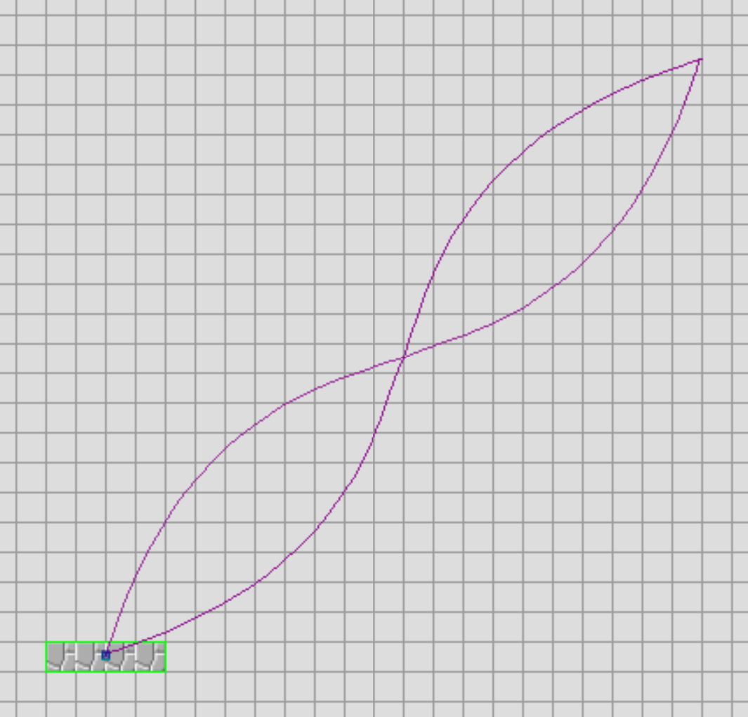
figure_8 {
type sine
controller timer_1
amplitude [ 5, 10 ]
frequency [ 3, 1 ]
phase [ 0, 0 ]
}
Sine movement components can be used to make circles, ellipses, figure-eights, or any other simlar shapes which are comprised of sine- or cosine-based movement. Sine movement components have both an x and y component. This is done to allow more easily configuring the relationship between the axes and ensuring that cycles remain consistent. Additionally, it ensures that movement on both axes refers to the same timer. There are three values which can be tweaked to produce different movement shapes. These are Amplitude, Frequency, and Phase.
Amplitude
Amplitude specifies the distance of travel from the origin point on each axis. When x and y values for amplitude are the same, the result will be a circle of radius x (or y if you prefer). When amplitude values are different, the resulting shape is an oval.
Frequency
Frequency specifies the number of cycles each axis will complete during one full cycle of the movement component as a whole. What's relevant here is the ratio between the x axis and the y axis. Say for example that the x axis has a frequency of 2 while the y axis has a frequency of 1. This means that the platform completes a horizontal cycle in half the time it takes to complete a vertical cycle. Then the resulting shape produced by the movement component is that of a vertical figure eight. Likewise, we can add more loops by increasing the x frequency further, or we can create horizontal figure eights by increasing the y value when the x value is set to 1.
Fractional values can produce very odd results, and may produce discontinuities (jumps in position). For this reason, it is recommended that you stick to integer values. It is possible to create some cool shapes with fractional values, but you have to think carefully about the relationship between the frequency and y phase (an aspect of the cycle offset which will be explained in the following section) in order to prevent discontinuities.
Phase
Phase is given in two components, base phase and y phase (as opposed to simply x and y components). The base phase is applied to both the x and y axis cycles, while the y phase is computed relative to the x axis. Both of these offsets are normalized from 0 to 1 as a factor of 2pi. This is much more useful than using absolute numbers. Using a base phase allows the designer to shift the starting position along a sine movment component without affecting the shape of the movement component. The Y phase however, will change the shape of the movement component and the starting position. I would recommend playing with the phase of the movment component first in order to find the desired shape, and then use the base phase to adjust the starting point. Keep in mind that the direction of travel along the movement component is ostensibly controlled by the Y Phase, since all phase values from 0 to 0.5 mirror those from 0.5 to 1. Therefore, if you want to maintain the shape of a Sine MC and reverse the direction of travel, you only need to either add or subtract 0.5 from the phase.
There are a few basic y-phase values you need to know when getting started:
For a circle, use y-phase 0.25 (counter-clockwise) or 0.75 (clockwise)
For a figure eight, use y-phase 0 or 0.5
For any x:1 ratio of frequencies:
when x is even, use y-phase 0 or 0.5
when x is odd, use y-phase 0.25 or 0.75
Linear Splines
Linear splines are a bit simpler to conceptualize than sine movement, but the syntax is slightly more complicated. The linear spline is comprised of one or more points in space, which are defined relative to one another. They are essentially a series of instructions telling the movement component how far to move on each axis on each step of the spline.
linear_spline {
  type        linear
  controller  timer_1
  smoothing   steps
  points [
    [  5,  0 ]
    [  0,  5 ]
    [ -5, -5 ]
  ]
}
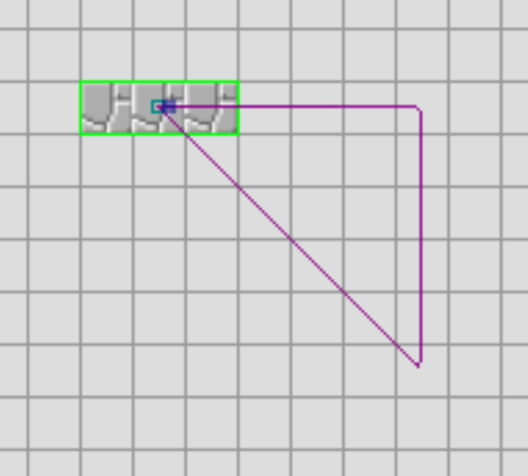
In the above example, we will move right 5 tiles, down 5 tiles, and then back up-left diagonally to the origin point. Don't let the nested array syntax mess you up, because it only gets worse with bezier splines.
Splines can also optionally have smoothing applied to them. The valid values for smoothing are "steps", "whole", or "none". Omitting this field, the value will default to none. As the names suggest, "steps" applies a smoothing over each individual step of the path and "whole" applies smoothing over the path as a whole.
Bezier Splines
Bezier splines are defined in much the same way as linear splines, however they require 3 points per step. The first point specified is the next critical point on the path, and the 2nd and 3rd points are the two control points for the bezier curve. If you want to better understand how bezier curves work, I recommend just watching whatever you can find on YouTube to explain the concept.
bezier_spline {
  type        bezier
  controller  timer_1
  smoothing   whole
  points [
    [ [ 20, -20], [15, -5], [  5, -15] ]
    [ [-20,  20], [-5, 15], [-15,   5] ]
  ]
}
Each step is an array of 3 points, each of which is a set of x and y coordinates. I recommend typing out your file in such a way that it's easy to see at a glance that you have the number of brackets and in the right places.
Pendulums
Pendulums are one of the simplest movement components to define overall. They have only a few parameters that you need to know.
pendulum {
  type        pendulum
  controller  timer_1
  frequency 1
  angle     50
  amplitude 14
}
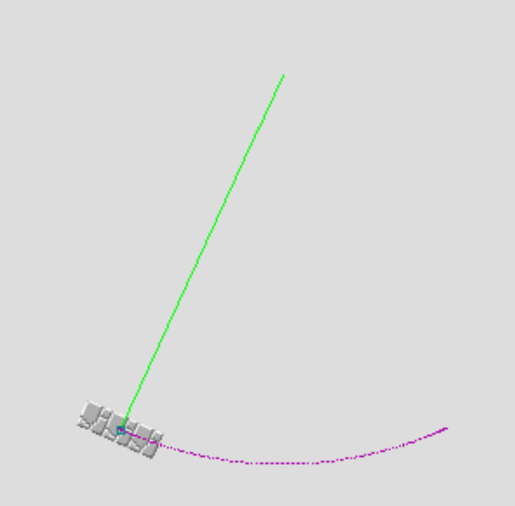
Frequency is the number of times the pendulum will cycle in one full cycle of its controlling timer. This variable makes it easier for you to coordinate multiple pendulums off of the same timer, as instead of using several timers which are mutliples of one another, you can just increase the frequency in the omvement component. Angle is how wide the swing of the pendulum is. So with a value of 50, the pendulum will swing 25 degrees in each direction. Amplitude is the distance that the pendulum "hangs" from the origin point. Think of it like the length of the chain that a chandelier hangs from.
Next time...
That's all I've got for this time. In the next post, I'll be talking about new types of timers, a little bit of the theory behind movement compontents, and maybe even rotations.